The electronics content of in-vehicle systems continues to grow as the market demands for automation, safety, energy optimization and high quality experiences. In this context, the number of applications using DC motors is also rising.
This article will analyze the market trends of automotive DC motors and explain why solid-state drives (SSDs) are better in terms of diagnostic functions, optimization of switching time, weight reduction, and (most importantly) improved reliability. Design architecture.
We will also specifically explain why the new VIPower M0-7 H-Bridge series is the best choice for all classes in all integrated circuits designed for automotive DC motor control.
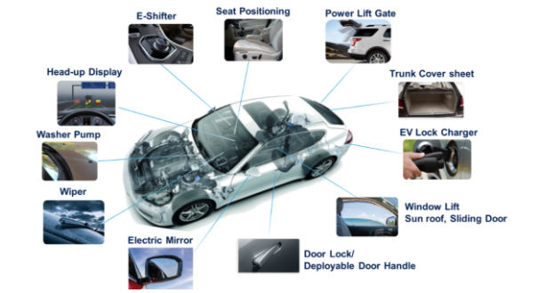 market trend
The demand for automotive DC motor systems is expected to grow steadily, with an annual growth rate of around 3.1% over the next five years. The demand around the body is mainly from traditional applications such as door locks, electric mirrors, seat adjustments, detergent pumps, wipers, window switches, sunroofs and electric sliding doors. But there are many new and appealing apps that are coming to market. Some examples include head-up displays (HUDs), hidden door handles, electric tailgates, electric car shifters and electric car charger locks.
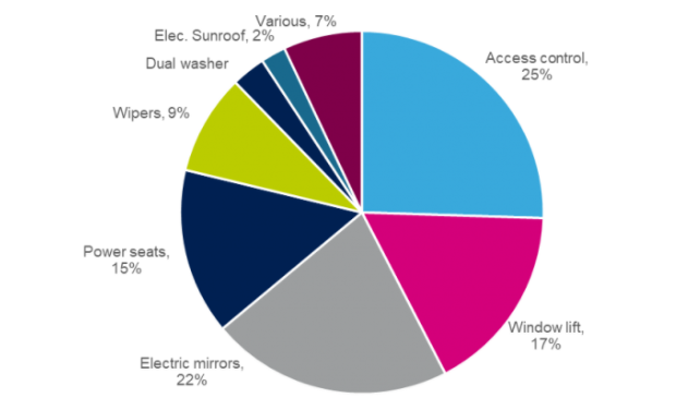
Considering the above situation, it is estimated that the demand for vehicle-related DC motors for vehicles in the world will reach 2 billion in 2020. The figure below shows the proportion of various applications, all applications consume between 30W and 200W.
Comparison of driving DC motors using relays and built-in chips in body applications
In the past, the automotive industry has always regarded relays as a simple and inexpensive solution for driving DC motors. But this idea is gradually changing, and now car manufacturers believe that SSD is the choice for new application design. Because of its highly reliable quality and enhanced diagnostic capabilities, SSDs can easily create innovative features such as driving a variety of variable load profiles (such as electric tailgates) or controlling the smoothness of movements (such as cars). Window switch or seat adjustment), eliminates relay switching noise and adds luxury.
Most importantly, local legislatures around the world have begun to set new limits on pollutants and carbon dioxide emissions from automobiles. The structure of the car must be adjusted, especially for the supply of power loads. More efficient electronic components must be used. . Although the target of the new standard will be dominated by a power-train system, the Body Control Module (BCM) is still partially related.
Therefore, we predict that the SSD-driven DC motors will grow by an average of 6.7% per year between 2020 and 2025, and will gradually grab the market share of relays.

In this case, ST's VIPowerTM M0-7 H-bridge series will be the best choice among the same class of components for motor control in automotive applications. The M0-7 H-Bridge Series combines logic and power architecture into a single package, allowing the chip's built-in intelligence to provide advanced diagnostics and protection, reducing the number of parts required, from providing simple drive protection to preventing faults. Improve reliability and save printed circuit board (PCB) area.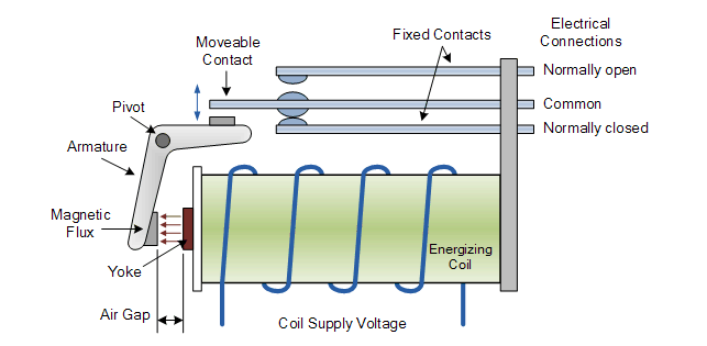
可靠度提升 进而延长10倍的使用寿命
继电器触点是一种可导电的金属片,相互连接好让电流通过。机械式开关触点常见的问题包括会听见噪音,还有终端顾客因为感受到机械震动而观感不佳(尤其是转换频率驱动应用)。除此之外,继电器切换时会造成电弧噪音,进而产生电磁干扰(EMI)。为了降低继电器切换噪音,就需要电阻电容减震器(RC snubber)和续流二极管(flywheel Diode)等额外零件,但这些额外零件会对最后结构的复杂性带来负面影响。切换时产生的机电应力,中长期的影响就是会降低接触电阻和效能,让继电器无法使用或缩短寿命。继电器效能的劣化则会降低可靠度。
固态切换器没有活动零件,因为机械式触点已被晶体管所取代:因此不会有电弧接触、磁场或可闻噪音等问题。输入控制兼容于大部份的IC逻辑系列产品,无须额外增加缓冲器、驱动器或放大器,可大幅降低印刷电路板的复杂性和面积。结果就是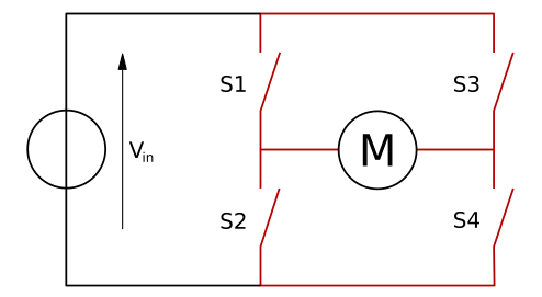
Increased reliability and extended service life by 10 times
The relay contacts are electrically conductive metal sheets that are connected to each other for current to pass. Common problems with mechanical switch contacts include the ability to hear noise, and the end customer's perception of mechanical shock (especially switching frequency drive applications). In addition, when the relay is switched, it causes arc noise, which in turn generates electromagnetic interference (EMI). In order to reduce relay switching noise, additional components such as RC snubbers and flywheel diodes are required, but these additional parts can have a negative impact on the complexity of the final structure. The electromechanical stress generated during switching, the medium and long term effect is to reduce the contact resistance and performance, making the relay unusable or shortening the life. Degradation of relay performance reduces reliability.
Solid state switches have no moving parts because mechanical contacts have been replaced by transistors: there are no problems with arcing, magnetic fields or audible noise. Input control is compatible with most IC logic families, eliminating the need for additional buffers, drivers or amplifiers, significantly reducing the complexity and area of printed circuit boards. The result is increased reliability and up to 10 times the exchange time.
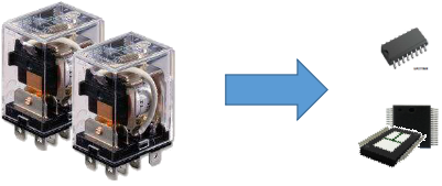
Finally, the design of the board cover and housing must also take into account the height of the relay, so it is generally necessary to maintain a vertical distance of 17 mm.
Taking into account the outstanding space-saving features of the VIPowerTM M0-7 technology, the ST-H-Bridge series can be built into the advanced compact power package: the SO-16N and the PowerSSO-36. The footprints of 60 mm2 and 106 mm2 can be reduced, respectively, and the thickness is less than 2.5 mm, making the printed circuit board smaller and the system also reducing weight. In addition, the VIPower® M0-7 H-Bridge provides an environmentally friendly product portfolio in a lead-free package that ensures outstanding heat dissipation. Finally, the design of the board cover and housing must also take into account the height of the relay, so it is generally necessary to maintain a vertical distance of 17 mm.
Switching time and pulse width modulation (PWM) control
When guiding the H-bridge architecture, special care must be taken to avoid unnecessary short circuits between the battery line and ground, especially during the switching phase; this condition is usually defined as a dynamic shoot through. Whenever a breakdown event occurs, the noise and power consumption of the battery line is additionally generated, thereby reducing system efficiency. This phenomenon becomes more serious if the H-bridge is driven by a fast switch such as a pulse width modulation signal.
Pulse width modulation input signals are often used to control the H-bridge architecture. As long as the duty cycle is changed, the motor speed and torque can be adjusted to build the following advanced features:
· Anti-pinch function;
· Smooth start and stop movements to enhance the driving experience;
· stall condition control;
· Motor speed regulation is not affected by battery voltage;
· Reduce the inrush current at the start
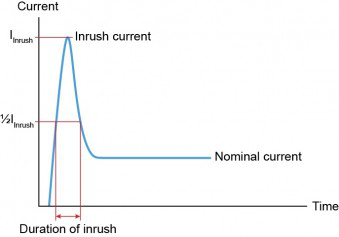
Generally, the DC motor profile will have a start-up period, and the inrush current is 10-12 times the normal current. All electronic components must meet specifications to withstand such high currents for a period of time, which will continue to affect the wire size, printed circuit board area, and drive function of the final application.
It is true that the relay specification only provides maximum contact rating for resistive DC loads, but this rating is greatly reduced by high inductance or capacitive loads.
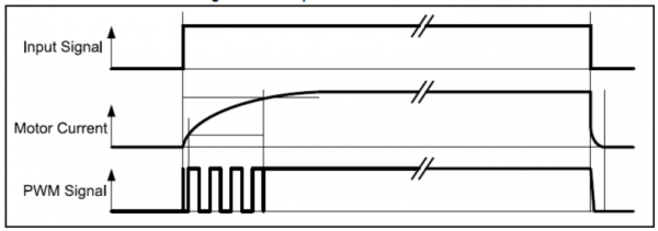
By driving the DC motor with a pulse width modulation signal, it is possible to achieve a smooth motor start with limited torque. The inrush current is also reduced, extending the motor start-up period. By driving the DC motor with a pulse width modulation signal, the power consumption can be optimized, and the wire size can be reduced, which is beneficial to reduce the weight as a whole.
Relays are not suitable for systems that require fast output switching. Switching times are limited by mechanical tip movement, typically between 5 milliseconds (ms) and up to 15 milliseconds. In addition, microcontrollers (MCUs) must implement appropriate logic protection to prevent unnecessary cross-conduction events.
The VIPowerTM M0-7 H-Bridge series guarantees fast switching times (typically 1 microsecond), ensuring switching frequencies up to 20 KHz. Switching profiles are specifically designed to optimize electromagnetic interference and switch losses. In addition, the chip also features special protection features to avoid dynamic and static cross-conduction problems. Therefore, the VNH7 series is designed to optimize system performance.
VIPowerTM M0-7 Series H-Bridge for DC Motor Control
The VIPower M0-7 H-Bridge series can be seen as a natural option for driving DC motors for vehicles, meeting the market's need for improved reliability, system efficiency and luxury. Thanks to the hybrid mode, the M0-7 H-Bridge series combines logic and power architecture into a single package, providing a complete portfolio of fully integrated and protected circuits. Because it offers different on-state resistances (from 8 mΩ up to 100 mΩ) and a small power supply package, this series ensures flexible driving and control functions, covering a wide range of load conditions (from poles) As low as 200W).

Although the low- and medium-power components integrate all logic functions and complete power stages, including high-side and low-side power metal oxide semiconductors (MOS), high power such as VNHD7008AY and VNHD7012AY The components are available in different architectures, including high-side power MOS and low-side gate drivers. Therefore, to complete the H-bridge architecture, there must be an external low-side power MOS (STB76DN4LF7AG is recommended).
The 20-kHz pulse width modulation speed control combined with diagnostics makes these products ideal for high-end automotive applications. The standby mode has low power consumption, up to 3 microamps (μA), and the switching profile during conversion is optimized, although it increases the number of electronic components on the board, but allows the module to maintain low power consumption.
By integrating advanced diagnostics (VCC voltage, case temperature and current load detection) and protection functions (overvoltage, short circuit, high temperature and cross conduction protection), both power levels and loads can be protected without affecting the final efficiency system. Make sure that the unit will always operate in a safe operating area. In addition, thanks to the shutdown status diagnostic function, the motor status can be monitored during the standby state to avoid possible damage during opening.
Combining the VIPower M0-7's intelligent power switching and H-bridge drivers in the body control module saves power consumption, printed circuit board area and cabling requirements. The actual result will be an increase in system reliability and an estimated weight of up to 50 kg per car, which will have a positive impact on pollution, including reduced CO2 emissions from internal combustion engine (ICE) vehicles (estimated up to 3.5g) /km), battery optimization, the automatic driving degree of pure electric vehicles (BEV) can also be improved.


 RCCN WeChat QrCode
 Mobile WebSite