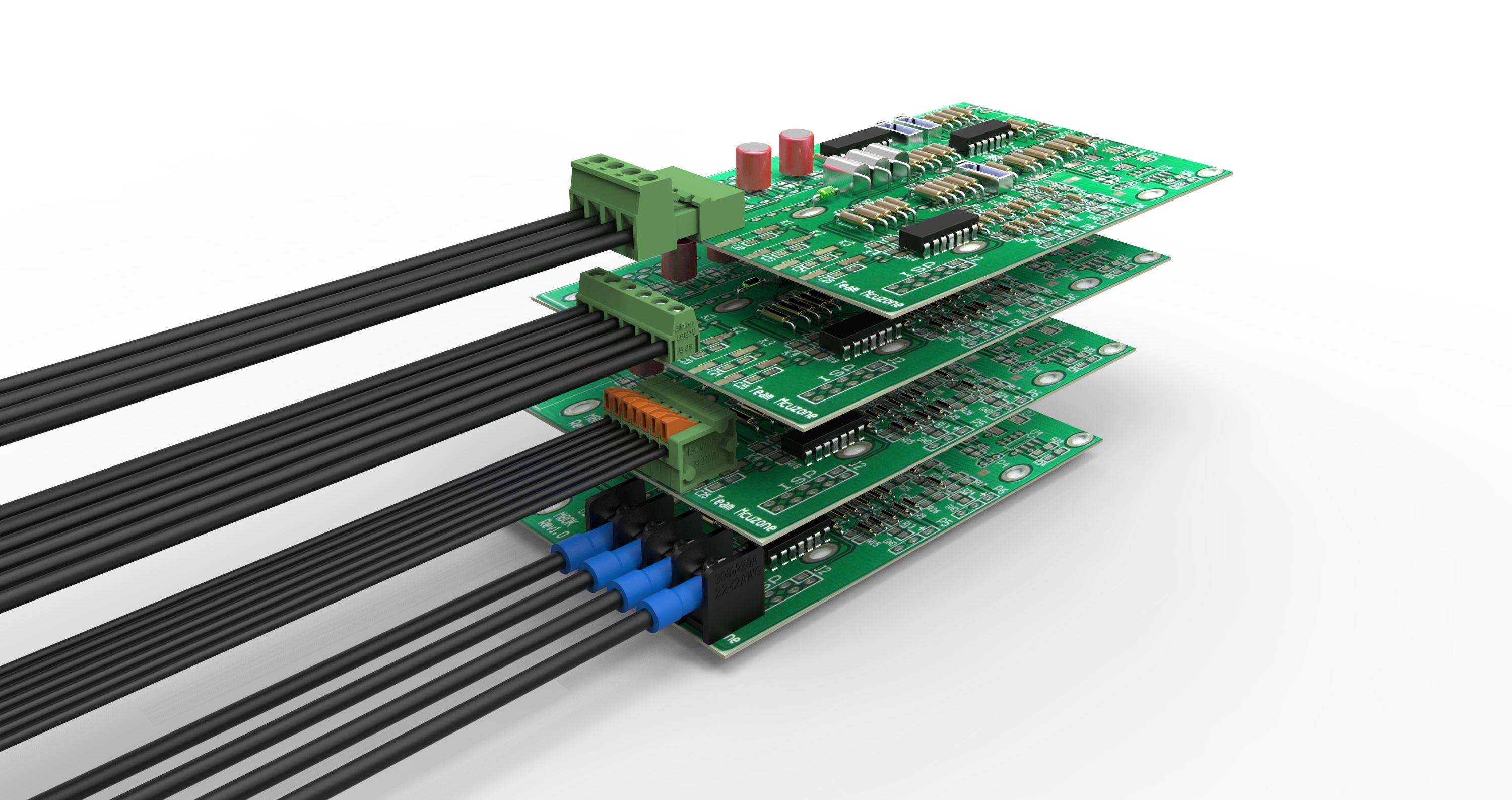
Terminal block plug-in series terminal block: It is made up of two parts plugged and unplugged, one part is pressed and then inserted into another part, which is soldered to the PCB board. This bottom mechanical principle, this anti-vibration design ensures long-term airtight connection and reliability of the finished product. The ears can be assembled at both ends of the socket. The mounting ears can largely protect the tabs and prevent the tabs from being placed in a poor position. At the same time, the socket design ensures that the socket can be correctly inserted into the maternal body. The socket can also have an assembly buckle and a locking buckle. The mounting buckles provide a more secure attachment to the PCB, and the locking tabs lock the parent and socket after installation. A variety of socket designs can be used with different mating methods, such as horizontal, vertical or tilted printed circuit boards, etc., depending on the customer's requirements. You can choose either a metric wire gauge or a standard wire gauge.
The terminal block is composed of an insulating base, an insulating partition and a wire component, and the insulating base is integrated. The wiring component is seated on the insulating base and placed in the insulating partition, and the wiring component comprises a wire clamp, a screw, a nut and a support frame. The support frame is U-shaped, the wire clamp is placed in the support frame, and the nut and the screw press the wire clamp along the elongated holes on both ends of the U-shaped support frame. The wire clamp is composed of the upper wire clamp and the conductive sheet, and the upper wire clamp surface is on both sides The protrusion has a plurality of rows of protrusions, and the protrusion has one or two ribs on the protrusion, wherein the upper surface of the conductive sheet has a plurality of rows of protrusions on both sides, and the terminal block protrusion and the middle portion of the upper surface form an arc, and one or two ribs on the arc surface The bump and the bump form a zigzag shape, and the middle portion of the upper surface of the conductive sheet is a convex platform, and the center of the platform is provided with a threaded hole and the insulating base is connected by bolts, and the two ends of the lower surface of the conductive sheet are respectively protruded by a positioning block and a U-shaped support. When the frames are connected, the two wire clamps on the two terminals of the terminal are respectively placed on the two sides of the conductive sheet platform and are clamped together with the conductive sheets, and the wire clamps on the terminal blocks and the conductive sheet bumps are clamped to each other.
The terminal block and the voltage terminal are; there is no difference between the voltage terminal and the current terminal. However, the wiring diagram of this watch should be paid attention to when wiring. (There is a general cover on the cover.) The main difference between the two types of terminals is the voltage terminal. Generally, the common terminal cannot be disconnected from itself. The terminal can only be disconnected through the connectable terminal. The terminal can usually be disconnected for testing.


 RCCN WeChat QrCode
 Mobile WebSite