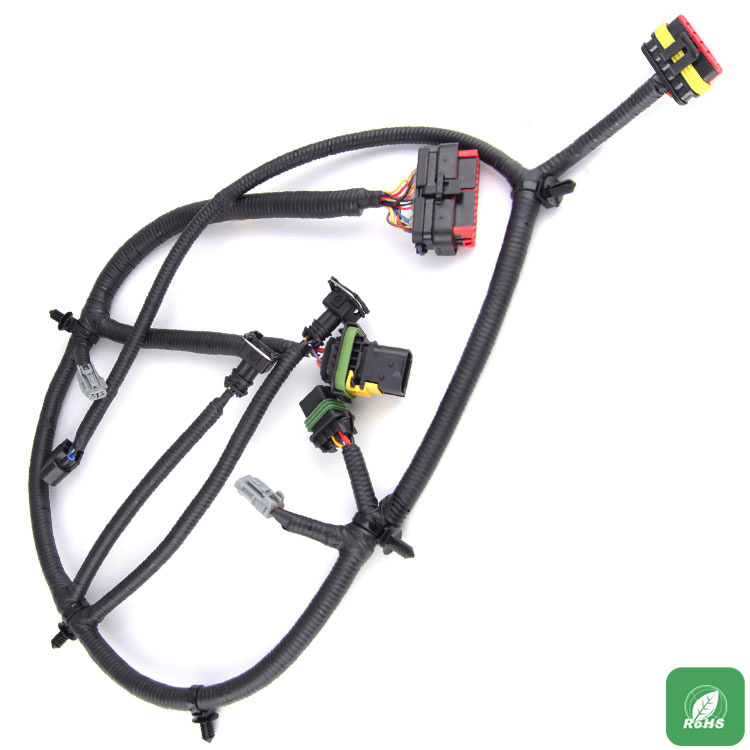
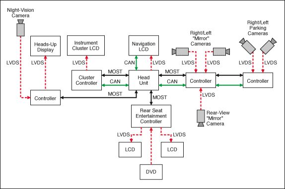
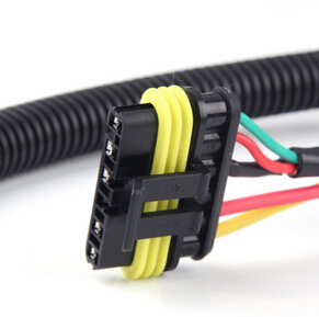
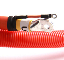
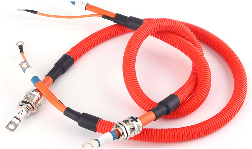
The harness diagram must be drawn before the wiring harness is arranged. The harness diagram is not the same as the circuit schematic. The circuit diagram is an image that represents the relationship between the various electrical parts. It does not reflect how the electrical parts are connected to each other and is not affected by the size and shape of the individual electrical components and the distance between them. The wiring harness diagram must take into account the size and shape of the various electrical components and the distance between them. The harness welding also reflects how the electrical components are connected to each other.
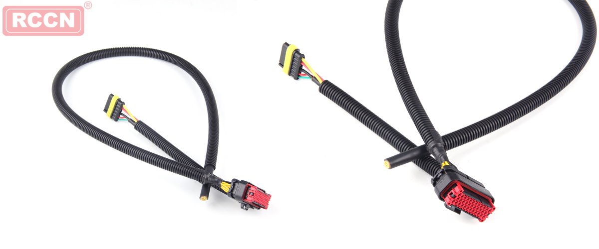
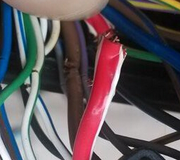
The wires used in automobile wire harness welding are commonly used in specifications with nominal cross-sectional areas of 0.5, 0.75, 1.0, 1.5, 2.0, 2.5, 4.0, 6.0, and other square millimeters of wire (the nominal cross-sectional area commonly used in Japanese cars is 0.5, 0.85, 1.25, 2.0, 2.5, 4.0, 6.0, and other square millimeters), each of which has a permissible load current value for use with conductors for different power consumers. Take the vehicle wiring harness as an example, the 0.5 specification line is suitable for instrument lamps, indicator lamps, door lamps, ceiling lamps, etc.; 0.75 specification line is suitable for license plate lamps, front and rear small lamps, brake lamps, etc.; 1.0 specification line is applicable to the steering lamp and fog Lamps, etc.; 1.5 specification lines are suitable for headlights, horns, etc.; main power lines such as generator armature lines, ground lines, etc. require 2.5 to 4 square millimeters of wire. This just refers to the general car, the key depends on the load of the maximum current value, such as the battery's ground wire, the positive power cord is a dedicated car wire alone, their wire diameter are relatively large, at least a dozen square millimeters Above, these "giant" wires will not be incorporated into the main harness.


 RCCN WeChat QrCode
 Mobile WebSite